Now that we have covered the brains of these two solutions, I feel it is time to compare and contrast the Edge (Ingress/Egress). Traffic has to enter and leave these environments and each solution performs these tasks differently. Below you will find a summary of what is the NSX Edge and what is Gateway and Software Defined Load Balancer. I’ve added some useful links to store for a later read.
Feel free to check in on this series:
Youtube videos you will find useful:
SDN Overview [youtu.be]
SLB [youtu.be]
NSX Edge
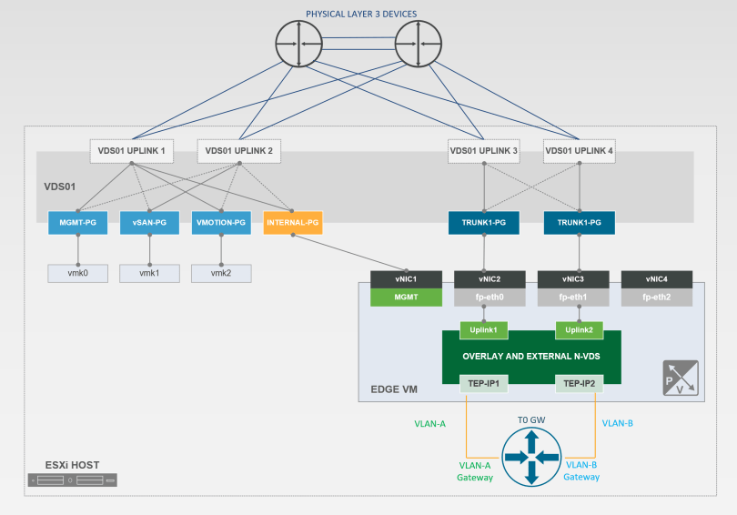
Above you will find the NSX Edge Virtual Machine Architecture.
From a high level you have a Tier-0 router (North/South Traffic) living on an Edge Virtual Machine with an embedded N-VDS which lives on top of the ESXi host. Below, I will break down each construct.
What is the Tier-0 router?
Tier-0 GW: Has a 1:1 mapping to an Edge VM (Require two (2) for ECMP/HA). T0 interfaces with the physical network via Dynamic Routing Protocols (BGP) to allow ingress/egress of traffic. This is done by creating interfaces on the T0 that is tied to VLAN backed segments which connect to the physical core.
The Tier-0 connects to the Tier-1 routing layer of the tenant routing topologies and receives routing information from the Tier-1. The Tier-0 pushes the default information down to the Tier-1 level. The Tier-0 is a virtual construct that lives in memory on the Edge VM shared across all the Transport nodes (ESXi hosts) in the environment.
Service Router (SR): whenever you activate any of the below services that cannot be distributed then a SR is instantiated on the Tier-0.
- North-South Routing
- NAT
- DHCP
- Load Balancing
- VPN
- Gateway Firewall
- Bridging
What is a N-VDS Switch?
in short, a software logical switch that provides the forwarding service on a transport node. Who owns it? The NSX Manager.
The first interface/vNIC is dedicated for Mgmt. traffic.
The second and third vNIC is dedicated to the datapath module (fp-ethX)
Since vSphere 7.X it is now supported to have virtual distributed switch connectivity
The fp-ethx interfaces are assigned to the overlay or external VLAN traffic. This would be your tunnel endpoint (TEP) traffic.
You need to either use predefined or create new edge uplink profiles to map the TEPs to the appropriate uplinks in the uplink profile.
What is a NSX Edge? Yes. 🙂
The NSX Native Load Balancer
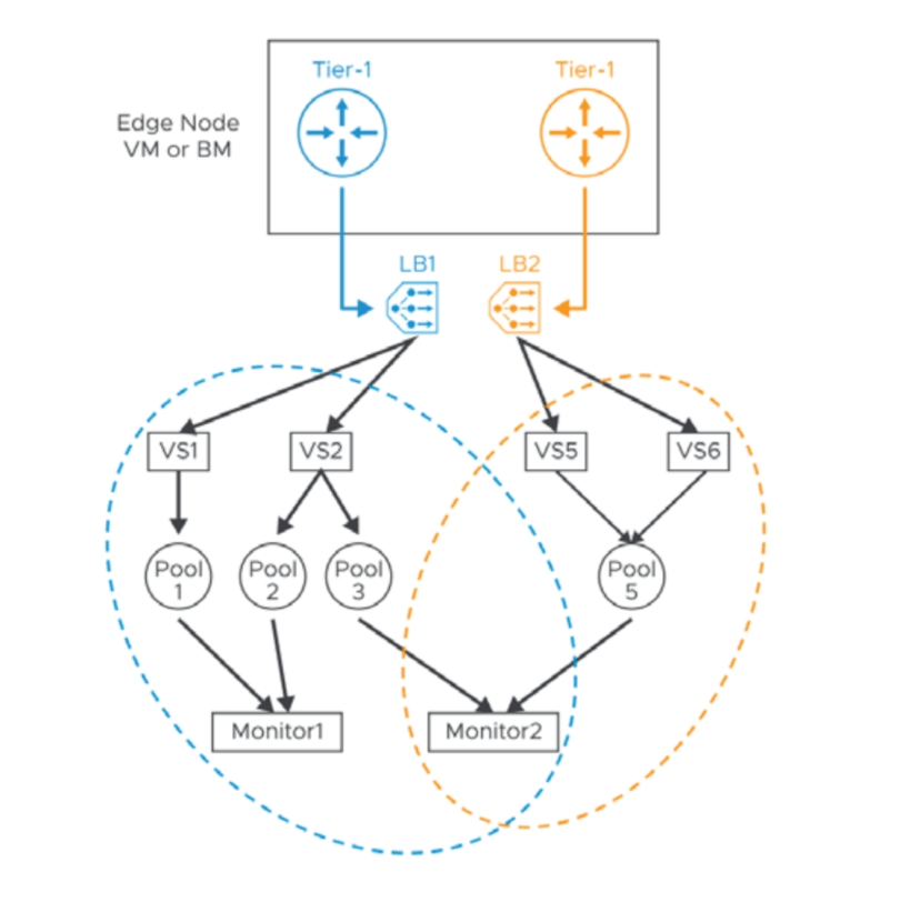
In the Edge VM section you didn’t hear me talk about load balancing. That is because the load balancer in NSX doesn’t control the ingress/egress of traffic from your virtual networks. They live behind the scenes, typically, deployed on Tier-1 routers (Distributed Routing function).
Quick review, a NSX Native LB is just a logical entity you create like any physical or virtual load balancer. The LB becomes realized when you attach it to a Tier-1 router and has a 1:1 relationship (logical router to load balancer). You have the ability to deploy in-line or one-ARM configuration.
In summary, the NSX does everything in your software defined networking environment when it comes to services and traffic ingress/egress your environment. There are a lot of design decisions that go into deploying edges, mainly around throughput and multitenancy. However, I plan to save that for another blog article.
For more information on the NSX Edges and Components, please see the below links:
https://docs.vmware.com/en/VMware-NSX/4.1/administration/GUID-FBFD577B-745C-4658-B713-A3016D18CB9A.html
https://nsx.techzone.vmware.com/api/checkuseraccess?referer=/sites/default/files/NSX-T%20Reference%20Design%20Guide%203-0.pdf
Azure Stack SDN Edge
I know the above name can be deceptive because in SDN there are two (2) ways to ingress/egress the network. You have the Software Defined Load Balancer (SLB) and you have the Gateway (Primarily the L3 GW). You were probably wondering why I mentioned the NSX LB? In SDN you have the ability to setup router interfaces on the load balancers, which you cannot do in NSX.
The Software Defined Load Balancer (SLB)
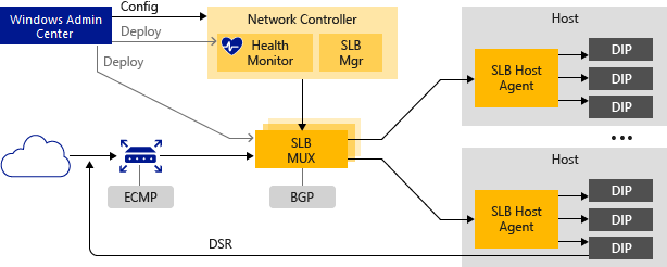
The above is how the different agents/services communicate in order to ensure the packet reaches its desired destination. I plan to release a more detailed article later covering this.
When you first deploy SDN you have point in fact deployed an isolated silo. What if you want traffic to in or traffic to leave your silo? At a minimum you need to deploy a Software Load Balancer. Yes, the L3 gateway is optional!
SLB enables multiple servers to host the same workload, providing high availability and scalability. The SLB constructs live on their own virtual machines. We deploy a minimum of three (3) for high availability in a SLB pool.
Software Load Balancer includes the following capabilities:
- Layer 4 (L4) load balancing services for north/south and east/west TCP/UDP traffic.
- Public network and Internal network traffic load balancing.
- Dynamic IP addresses (DIPs) support on virtual Local Area Networks (VLANs) and on virtual networks that you create by using Hyper-V Network Virtualization.
- Health probe support.
- Ready for cloud scale, including scale-out capability and scale-up capability for multiplexers and host agents.
Software Load Balancer works by mapping virtual IP addresses (VIPs) to DIPs that are part of a cloud service set of resources in the datacenter.
VIPs are located in the SLB Multiplexer (MUX). The MUX consists of one or more VMs. Network Controller provides each MUX with each VIP, and each MUX in turn uses Border Gateway Protocol (BGP) to advertise each VIP to routers on the physical network as a /32 route. BGP allows the physical network routers to:
- Learn that a VIP is available on each MUX, even if the MUXes are on different subnets in a Layer 3 network.
- Spread the load for each VIP across all available MUXes using Equal Cost Multi-Path (ECMP) routing.
- Automatically detect a MUX failure or removal and stop sending traffic to the failed MUX.
- Spread the load from the failed or removed MUX across the healthy MUXes.
Finally of note, one massive value add would be the SLB’s capability to perform inbound/outbound NAT such as Inbound for a Jump box/Similar Azure Bastion service or Outbound for Internet access to a collection of VMs over a single PIP.
For more information on the Azure SDN SLB and Components, please see the below links:
https://learn.microsoft.com/en-us/azure-stack/hci/concepts/software-load-balancer#how-software-load-balancer-works
https://learn.microsoft.com/en-us/azure-stack/hci/deploy/sdn-wizard#deploy-sdn-software-load-balancer
The SDN Gateway (GW)
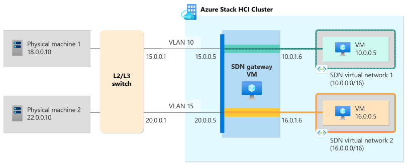
The above image is what you would expect to see from a L3 GW which is the majority of the use cases I see people deploying today.
RAS Gateway is a software-based Border Gateway Protocol (BGP) capable router designed for cloud service providers (CSPs) and enterprises that host multitenant virtual networks using Hyper-V Network Virtualization (HNV). You can use RAS Gateway to route network traffic between a virtual network and another network, either local or remote.
For HA it is recommend to deploy three (3) gateways in a M+N (This means that ‘M’ number of active gateway VMs are backed up by ‘N’ number of standby gateway VMs) configurations.
The three (3) flavors of RAS Gateways you can deploy:
Site-to-Site IPsec VPN – This RAS Gateway feature allows you to connect two networks at different physical locations across the Internet by using a Site-to-Site (S2S) virtual private network (VPN) connection. This is an encrypted connection, using IKEv2 VPN protocol.
Site-to-Site GRE tunnels – Generic Routing Encapsulation (GRE)-based tunnels enable connectivity between tenant virtual networks and external networks. Because the GRE protocol is lightweight and support for GRE is available on most network devices, it’s an ideal choice for tunneling where encryption of data isn’t required.
Layer 3 forwarding – Layer 3 (L3) forwarding enables connectivity between the physical infrastructure in the datacenter and the virtualized infrastructure in the Hyper-V network virtualization cloud. By using L3 forwarding connection, tenant network VMs can connect to a physical network through the Software Defined Networking (SDN) gateway, which is already configured in the SDN environment. In this case, the SDN gateway acts as a router between the virtualized network and the physical network.
I am mainly going to focus on the Layer-3 GW since this is the majority of what I see. RAS Gateway routes network traffic between the physical network and VM network resources, regardless of the location. You can route the network traffic at the same physical location or many different locations.
I easiest way to look at this would be to image you have a Virtual Network with Virtual Subnets living in your SDN. A virtual machine living in your vNET needs to communicate with a shared service virtual machine that may live outside of the vNET. You can deploy a GW pool with BGP peering to the physical core network that your packet will go from your SDN VM to the core onto its destination. This is providing true flexibility while allowing your Zero Trust network the ability to run within SDN.
For more information on the Azure SDN GW and Components, please see the below links:
Summary:
Whether you are on NSX or Azure Stack SDN, you will require a way to communicate with your physical network. NSX offers you the Tier-0 GW and SDN offers you SLBs and GWs. Personally, I like the flexibility SDN provides because I am an options kind of human. In SDN I believe this offers even greater design options for your overlay/virtual networks vs NSX that has a variety of gateway options based on your multitenant needs.
*The thoughts and opinions in this article are mine and hold no reflect on my employer*