If you’ ve been working with VCF, NSX and vSphere, you are probably used to thinking about virtual machines in terms of vMotion, VLANs, overlay segments, Tier-0/Tier-1 gateways, VPCs and so on. But what happens when the VM you want to run on VCF is not a normal application server? What if that VM is actually a PLC (Programmable Logic Controller) controlling a production line in cars factory?
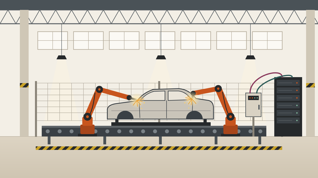
A normal VM can usually tolerate some variation in network latency. A PLC controlling a robot cannot necessarily do that. A few milliseconds of additional delay or unpredictable jitter may be irrelevant for a db server, but can be important for an industrial control system. This is where Industrial vSwitch (IvS) comes into the play.
IvS was introduced with VCF 9.0 as a specialized networking capability for industrial workloads. Its main purpose is to allow virtual PLCs (vPLCs) running as VMs on VCF workload domain to communicate with physical industrial I/O devices using PROFINET, while providing the low latency, bounded jitter and Layer 2 behavior required by industrial automation.
NOTE!!! I wrote this post while getting familiar with IvS and trying to put together what I’ve learned so far. I work with VCF every day, but industrial networking was new to me. When I started reading about IvS and when I had to deal with this topic for one of my clients, I quickly realized I couldn’t understand it without first understanding what a PLC is, why anyone would want to virtualize one, and what PROFINET actually does on the wire. Most IvS material assumes you already know the factory side. I am writing this article from the perspective of someone who is coming into this topic from the VCF/NSX side rather than from the industrial automation world. If you spot something that is inaccurate or could be explained better, I’d be very happy to hear about it.
So let’s start from the beginning.
Question No 1: what is a PLC?

Let’s forget VMware for a moment. A PLC – is essentially a computer used to control an industrial process. Imagine a car factory. You might have a robot that detects a car body, moves its arm, starts welding, checks sensors, moves to another position, waits for another machine and then continues.
Something needs to coordinate all of this. That “something” can be a PLC. A PLC works in a repeating cycle, often called the scan cycle:
- Read all inputs (sensor states, values from drives and robots)
- Execute the control program using those inputs
- Write all outputs (commands to actuators, drives and robots)
- Repeat
On a networked PLC, steps 1 and 3 happen over the network: input and output data are exchanged with I/O devices at a fixed interval, for example every few milliseconds.
A simple example: a robotic welding cell
Imagine a cell where a car body arrives on a conveyor, gets clamped, and two robots weld it:
- A sensor tells the PLC the body has arrived.
- The PLC stops the conveyor and closes the clamps.
- Clamp sensors confirm they are closed.
- The PLC tells both robots to start their weld programs.
- The robots report “done”; the PLC opens the clamps and starts the conveyor.
Also running all the time: safety inputs. If someone opens the cell door or breaks a light curtain, the robots must stop. This happens extremely quickly and repeatedly. That is why the network between the PLC and the devices is not just a normal network.
Why timing matters
In an office application, “the response arrived a bit late” means a slow web page. In a PLC, the control logic assumes it has a fresh picture of the machine every cycle. If input data arrives late, the PLC is making decisions on stale information. If output data arrives late, the machine reacts late.
Industrial protocols are designed to detect this. If expected cyclic data does not arrive within a configured watchdog time, the connection is treated as failed and the devices go to a safe state. On a real line, that means the cell stops, and someone has to restart it. A few milliseconds of network delay can turn into minutes of lost production.
Question No 2: what is a vPLC?
Simple answer- vPLC is a PLC software running as a workload on server hardware instead of on a dedicated PLC box. The control program is the same kind of program; what changes is where it runs. So with a physical PLC, the path is short and the hardware belongs to one machine. So long story short: vPLC VMs run in a dedicated VCF workload domain cluster that acts as the control layer for the factory floor. NSX Manager, vCenter and other VCF appliances stay in the management domain. Each vPLC gets its own NSX VLAN segment that reaches its robot cell on the shop floor.
With a vPLC on VCF, the path has a few more layers, and every one of them is something you usually manage:
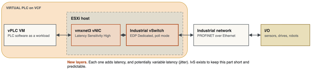
That middle part (vmxnet3 vNIC, the host switch, the physical NIC, the uplink) is exactly where virtual world and the factory world meet. Every layer adds a little latency, and more importantly, every layer can add variable latency.
The penultimate element of the diagram is PROFINET. So what is PROFINET? This is where we need to leave the VMware terminology for a moment. PROFINET is an industrial Ethernet communication protocol. It is used to exchange information between things such as PLCs, remote I/O, sesnors, drives, robots etc. It is very important to understand one thing that PROFINET is not the same thing as Ethernet. Ethernet is the underlying network technology. PROFINET is the industrial communication protocol that uses Ethernet. It can also use standard TCP/IP for functions such as configuration, diagnostics and parameterization, but its real-time communication mechanisms are different.
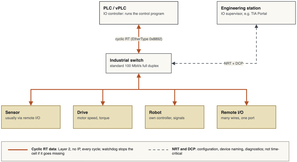
I’ll get back to the PROFINET later on this blog. So now lets get back to virtual world again.
Why manufacturers want to virtualize PLCs
- Faster recovery when a controller fails (restart on another host instead of swapping hardware)
- Software-delivered features and faster updates
- Centralized management and operations
- Standardized software stacks, which helps security and lifecycle management
- Consolidation, with up to 12 vPLCs per host
In a plant with hundreds of PLC cabinets, each with its own hardware, firmware and spares, that is a strong argument. The harder part is that a PLC was never designed to share hardware. Moving it onto a hypervisor raises questions we don’t usually ask:
- Operations: Broadcom notes that bounded latency is not guaranteed during vMotion, software upgrades or configuration changes. Maintenance windows still matter.
- CPU scheduling: the vPLC’s control loop must run on time, every cycle. That is why vPLC VMs need Latency Sensitivity set to High.
- Network determinism: the cyclic frames must leave and arrive within a tight window, every cycle.
- Redundancy: a single NIC or switch failure must not stop the production line.
Why ‘normal’ vDS is not necessarily enough
If I take a VM and connect it to a virtual switch, why can’t I just run a PLC there? From a VMware administrator’s perspective, this looks perfectly reasonable. But industrial automation has a requirement that normal IT applications usually don’t have predicatble timing. For a control system, the occasional 2 ms delay may be very important.
Latency, jitter and determinism
Three terms come up constantly in the industrial material:
- Latency is how long a frame takes to get from A to B.
- Jitter is how much that latency varies from frame to frame.
- Deterministic means the behavior is predictable: packets arrive within a predictable time range
Why average latency is not enough. Look at two series of four measurements.
The first: 100 µs, 101 µs, 99 µs, 102 µs
The second: 100 µs, 101 µs, 99 µs, 1500 µs
The first averages about 100 µs. The second averages 450 µs, which on a dashboard might still look acceptable. But if the control cycle is 1 ms, that one 1500 µs frame arrived after the next cycle had already started. The PLC worked with old data for that cycle, or an output was applied late. One late frame usually isn’t fatal on its own: PROFINET tolerates a configured number of missed cycles before it declares the connection lost. But if spikes repeat, or cluster together (for example during a CPU contention burst), the watchdog expires and the I/O devices go to their safe state. The production cell stops. The analogy that worked for me: a train timetable. Nobody cares that the average train is on time if the one you needed was 40 minutes late. Industrial control cares about the maximum, not the mean. That is why IvS reports maxLatency per vNIC rather than an average.
Now lets get back to PROFINET again. This protocol has different types of communication. Not every PROFINET packet is necessarily “real-time.” There are several communication mechanisms. The simplest way to understand them is:
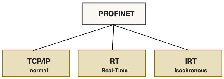
- Normal TCP/IP is used for things such as configuration, diagnostics, parameterization, engineering, communication with higher-level systems. This traffic isn’t necessarily time-critical. If the configuration packet takes an extra millisecond to arrive, nobody cares.
- Then we have PROFINET RT — Real Time. This is used for time-critical cyclic communication. PROFINET RT is optimized so that the real-time Ethernet frame does not have to go through the normal TCP/IP processing path. PROFINET RT frames use Ethernet EtherType
0x8892. For a VMware engineer, this has a practical consequence: RT traffic is pure Layer 2. It cannot be routed. The vPLC and its I/O devices must be in the same broadcast domain, which is exactly why the IvS design maps each vPLC to a VLAN segment that extends to its robot cell. . According to the PROFINET organization, RT satisfies the timing requirements of the vast majority of industrial automation applications. So in many industrial environments PROFINET RT (real-time) is the thing you actually need.
- There is also PROFINET IRT — Isochronous Real Time. IRT is used for applications where extremely precise synchronization is required, particularly demanding motion-control applications. PROFINET documentation describes IRT as the option for the most demanding applications, with sub-millisecond cycle times and very small jitter. But this is important: Do not assume that every PROFINET application requires IRT. The PROFINET organization states that RT meets the requirements of most applications, while IRT is optional and used for more demanding use cases. IRT depends on hardware-scheduled time slots and clock synchronization in every hop, and nothing in the current documentation says IvS participates in that. If your application needs IRT (typically synchronized motion control), confirm with Broadcom and your PLC vendor before designing around IvS.
Where does Industrial vSwitch (IvS) come into this?
Now we can finally connect PROFINET with VMware. IvS sits between the vPLC and two indepenednt LANs to the cell. If I had to explain IvS to somebody who knows VCF but doesn’t know industrial networking, I would saythat IvS is a specialized NSX virtual switch designed to connect virtual PLCs running on ESXi to physical PROFINET devices while keeping the network path as predictable and low-latency as possible. It is specifically designed around the requirements of the industrial workload.
Each vPLC VM sends PROFINET traffic through the Industrial vSwitch on its ESXi host, which acts as a PRP RedBox and sends every frame over two independent LANs to a PRP-capable switch in the robot cell. This is based on the sample deployment in the VMware launch blog.
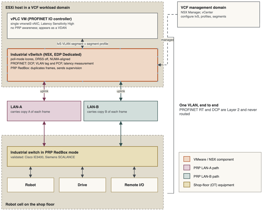
Everything from the vPLC to the robot is one Layer 2 VLAN; the IvS is the only component that is both PROFINET-aware and PRP-aware on the VMware side.
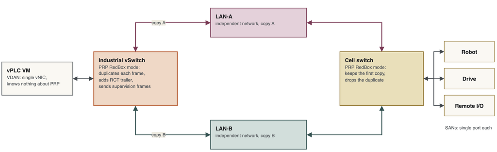
Following one cyclic frame
- The vPLC’s control program finishes a cycle and writes output data to a PROFINET RT frame (EtherType 0x8892) on its vmxnet3 vNIC.
- An EDP Dedicated lcore, polling continuously, picks the frame up from the vNIC almost immediately.
- The IvS applies the segment’s VLAN tag and keeps the PROFINET priority (PCP), and records the vNIC-to-uplink latency.
- Acting as a RedBox, the IvS duplicates the frame, adds the PRP trailer, and sends one copy out the LAN-A uplink and one out the LAN-B uplink.
- Both copies cross separate physical networks to the robot cell.
- The cell switch, also a RedBox, keeps the first copy, discards the second, and delivers the frame to the drive.
- The drive replies with input data, and the same path runs in reverse: the IvS accepts the first copy from either LAN and hands one frame to the vPLC.
If LAN-A fails at any point, step 6 simply uses the LAN-B copy. Nothing has to reconverge.
vPLCs are connected to dedicated NSX VLAN segments that correspond to the industrial networks used by the robot cells. This is actually quite easy to understand from a VMware perspective. You are essentially using NSX VLAN segments to connect the vPLC VM to the appropriate physical industrial VLAN. The difference is what happens on the host: the IvS datapath is used rather than a normal general-purpose networking path. And here PRP — Parallel Redundancy Protocol — also comes in. Look at the diagram above once again. PRP sends every frame twice, over two completely independent networks, and the receiver keeps whichever copy arrives first. If one network fails, nothing has to fail over, because the other copy is already on its way. IvS uses PRP to give vPLCs this protection.
How the pieces map to VCF objects
| Concept | VCF / NSX object |
|---|---|
| Control cluster for the factory | Dedicated cluster in a VCF workload domain |
| Industrial vSwitch | VDS created with the Industrial vSwitch option, onboarded through a Transport Node Profile |
| Where the PROFINET VLANs live | NSX VLAN transport zone and VLAN segments, one per vPLC/cell |
| PROFINET and PRP behavior per VLAN | IvS segment profile attached to the segment |
| LAN-A and LAN-B | Host uplinks annotated as LAN-A / LAN-B in the IvS PRP settings |
| EDP Dedicated cores | CPU config in the Transport Node Profile advanced settings |
| Management plane | NSX Manager and vCenter in the management domain |
IvS uses the NSX Enhanced Data Path (EDP) architecture and this is an important part of the story. IvS uses EDP Dedicated mode, which uses CPU polling for packet processing. VMware specifically identifies EDP Dedicated as the foundation used to achieve the latency and jitter characteristics required by the IvS use case. So the objective is make packet processing more predictable.
Why is CPU polling important? This is another concept that may be unfamiliar if you normally work with VCF. Normal networking can use hardware interrupts to tell the CPU: “There is a packet waitin”. With polling, the CPU actively checks for packets. It’s technique where a processing core continuously checks a network interface or memory ring buffer for new incoming or outgoing data packets rather than waiting for a hardware interrupt from the NIC. This consumes CPU resources, but it can provide a more predictable processing path.
PROFINET DCP: how devices find each other
In the red box inside the diagram above, you can find a PROFINET DCP. It’s the L2 protocol that engineering tools and controllers use to find PROFINET devices and assign them a name and IP address. In PROFINET, a device’s identity is its device name (for example factory1-cab1), not its IP address. The engineering project says “the controller talks to the device named cell05“. At startup, the controller finds that name on the network and makes sure the device has the IP address configured in the project. The closest IT analogy is ARP: DCP resolves a name to a MAC address on the local segment, then configures the device. DCP is also a link-layer protocol, so it only works within the broadcast domain.
Why DCP matters to IvS? If DCP frames don’t get through, the vPLC can never find its devices, and cyclic traffic never starts. Engineers also use DCP from TIA Portal to browse and name devices during commissioning. Because DCP relies on multicast and Layer 2 adjacency, it has to work correctly across the virtual switch, the VLAN segment and the physical industrial network.
Some of the requirements
Use a dedicated workload cluster. A dedicated cluster gives you much better control over CPU placement, NUMA, NICs, ESX config, firmware, miantanance capacity and workload placement. What NICs can be used? This is where we need to be careful. You cannot simply assume that every NIC supported by ESX is automatically suitable for IvS. The NIC used as an IvS uplink must support NSX Enhanced Datapath — Dedicated.
If you start troubleshooting IvS, you will probably encounter DRSS– Default Queue Receive Side Scaling. In normal high-performance networking, distributing incoming traffic across multiple hardware queues can be beneficial. But IvS is trying to create a predictable packet-processing path. Therefore Broadcom specifically documents that DRSS must be disabled on NICs used by IvS. And here predictability is more important than simply pushing as many packets as possible through the NIC.
NUMA becomes very important as well. If the vPLC runs on NUMA Node 1 but its industrial NIC is attached to NUMA Node 0, the packet path may have to cross the NUMA boundary. That can introduce additional latency.
Configuring IvS touches four layers: the server BIOS and ESX, vCenter, NSX and the vPLC VM but this is something that should be described in a dedicated post:)